CAD & Engineering Visualisation
Mechanical Movement Study
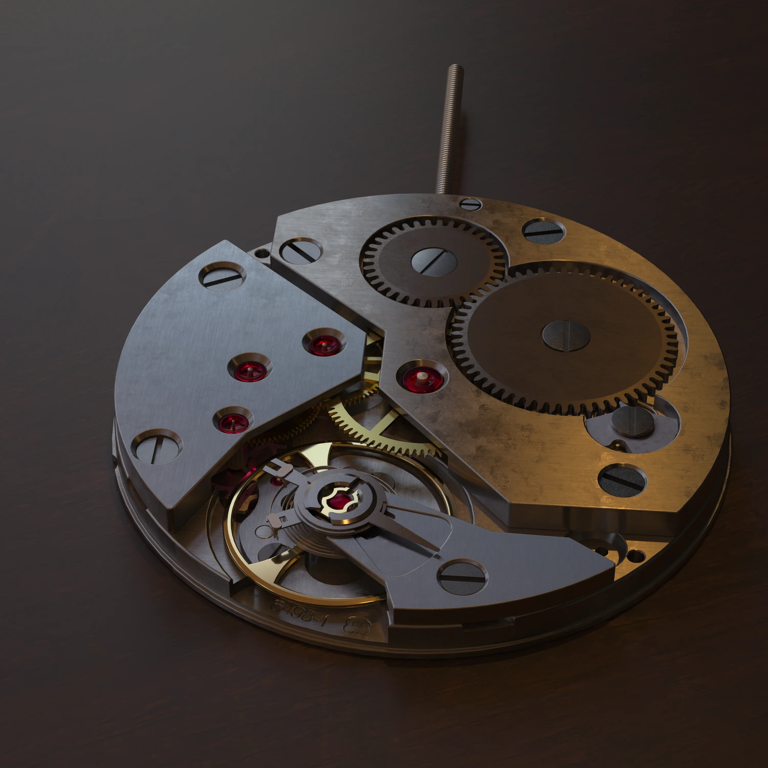
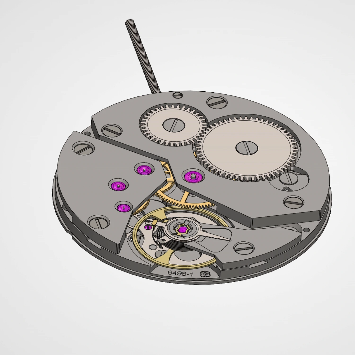
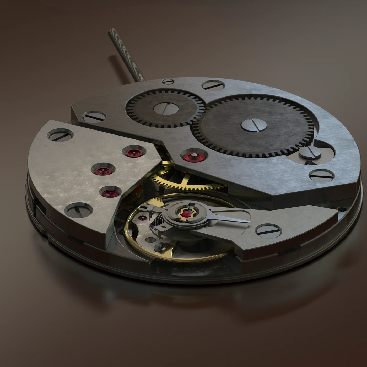
Precision CAD geometry taken to photoreal presentation — the clearest demonstration of the bridge between engineering data and finished visuals.
The problem
CAD data describes a mechanism exactly, but a shaded viewport says nothing about how the object will look, feel or sell. The task was to take precision geometry to photoreal presentation without losing dimensional truth.
What we solved
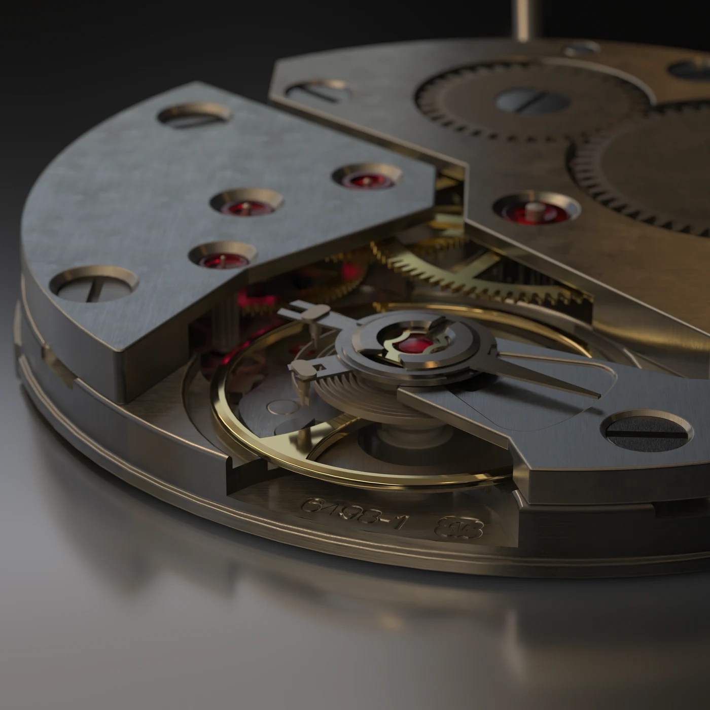
The CAD assembly was prepared for visual work, then material development did the heavy lifting: brushed and polished steel, brass wheels, blued screws and ruby jewels, each with its own surface response. Lighting was built for macro scale, and the mechanism was animated so the gear train reads as a working movement rather than a static model.
The result
A study that shows both ends of the workflow side by side — the CAD input and the photoreal output — alongside an animation that makes the mechanism legible.